
 Posted in
  Tags:
Tags: Source: CarAudioHelp
Problem: Acura Legend door locks that cycle many times when locked (usually) or unlocked. Cycling eventually stops but the problem remains. Problem is independent of how the doors are locked (key, switch or manual plunger).
Cause: The rubber bumper(s) inside the driver’s door lock mechanism that stops the lock or unlock cycle breaks and falls off.
Dealer Solution: Replace the entire lock mechanism at a cost of $300 for the part and $200 for the labor.
DIY Solution: Repair or replace the bumpers inside the mechanism. Cost is your time and maybe some scraped knuckles.
Disclaimer: Use these directions only as a guide and at your own risk. You’re responsible for any damage you do to the vehicle so BE CAREFUL. Your vehicle may in fact have slightly different methods so use common sense if the directions don’t match what you see. The demo vehicle being shown is a 1993 Acura Legend Coupe.
Click on the thumbnail images to see full size versions
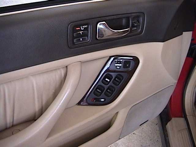
Step 1: Roll the window all the way up and then remove the driver’s door panel. Removal depends on model year and style but on the 93 Acura Legend Coupe this tutorial was done on there were four screws and a row of plastic push tabs along the perimeter of the door panel. This process can be done without removing the window but I have done it both ways and find removing the window gives much more room to work. This is the way I will show.
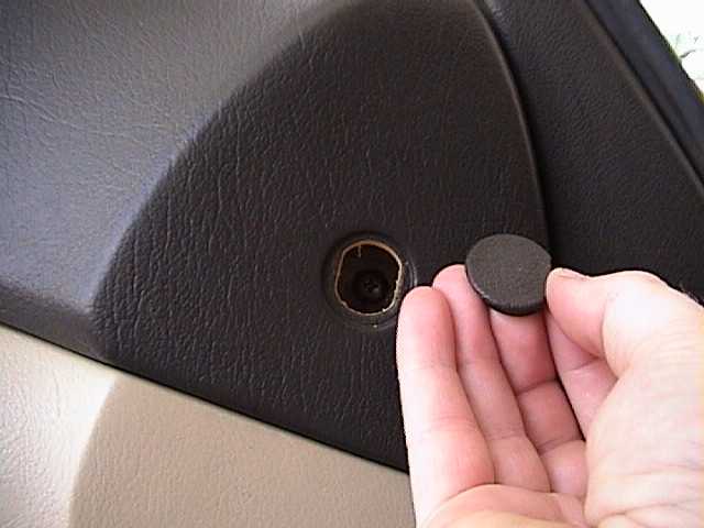
One of the screws is located behind a plastic cover near the front and top of the door panel. This cover can only be seen with the door open. Otherwise it is hidden by the side of the dash. Pry this cover up with a small screwdriver and remove the Phillips screw that is behind the cover.
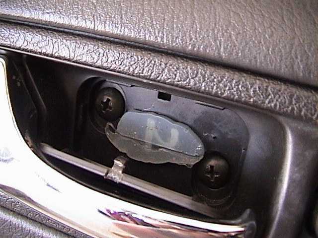
There are two more screws located behind a flat plastic panel that is also behind the inner door handle. Pry the cover off by inserting a small flat blade (eyeglass type) screwdriver into the notch at the top of the cover. Then rotate the cover down and towards you and put the small panel to the side. Remove the two Phillips screws. For the lower screw you will have to pull the door handle out in order to remove it.
The final screw is under another small, round plastic cover that sits horizontally near the bottom of the arm rest. It is visible from the top. Pry out this cover and remove the single Phillips screw.

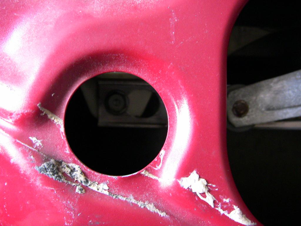
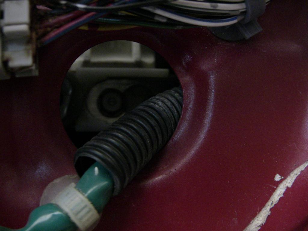
Now use a panel tool to pop the perimeter tabs out of the door. Once the entire door panel is free rotate it out slightly and pull up to unhook the top edge from the door. Unhook all of the wiring harnesses except those that are attached near the door panel switch. Turn the ignition key to the “Run” position and raise the window slightly until you see the window attachment bolts through the door. One will be accessible through the large door opening and the other will be accessible through a small access hole. Loosen but do not fully remove these (2) 10mm bolts (it’s OK if you do remove them completely). Note the way the window bolts attach to the bottom of the power window carriage mechanism. The bolts pass through a keyhole shaped notch. The mechanism slides so the round part of the hole will allow the bolt to pass through it. When the window is in place the mechanism needs to slide so the bolt attaches to the narrow end of the keyhole. Make note of how it goes back together as the mechanism can flop around and reverse itself. It’s easy to put back together but if it’s your first time it can be frustrating if you don’t know how it goes back.
 |
 |
|
Left Window Carriage Removal Hole
|
Right Window Carriage Removal Hole
|
Once the 10mm bolts are loosened and the mechanism slides out of the way you can free the window and pull it out of the door. This is best done by tilting the rear/top of the window forward and out of the rear window channel/track. Then pull the window up at this tilted angle. The still attached 10mm bolts will pass through an indentation in the top of the door panel. Both bolts pass through the same hole (one at a time, rear bolt first). Use caution that you don’t scrape the window as it passes through the door. This is especially true if you have tinted windows.
Now raise the window carriage to the top position and remove the ignition key. Unhook all of the wiring harnesses from the door panel. To remove the door handle release cable rotate it out of the slot on the back of the inner door handle. Then use a small pliers to pop the bare cable out of the plastic bushing. Finally pull the cable up and out of the bushing. You can now set the door panel to the side.
 |
 |
 |
 |
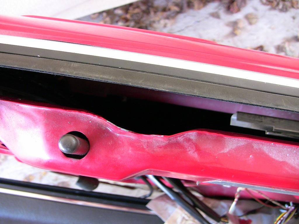
Step 2: Carefully peel back the plastic weather sheeting from the door in the area of the lock mechanism. Unplug the three harnesses in the photo below and then detach them from the door panel. To do this, reach in from the inside of the door and squeeze the plastic tabs together. Don’t try to force them out with a screwdriver or by hand. You’ll just end up breaking them off and then the wiring won’t sit in the door correctly. If you do break them they can be repaired with some success using super glue.

Step 3: Remove the bolt that holds the bottom of the window track in place.
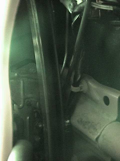
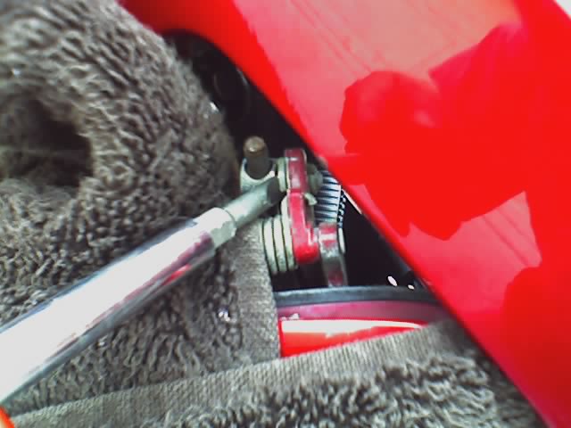
Step 4: Take a look inside as best you can at the lock mechanism and see how it attaches to the door handle and door. Here are some night vision shots of the area. Keep in mind that these are shots of the Acura Legend Coupe and that the door handles on an Acura Legend Sedan will attach differently.
 |
|
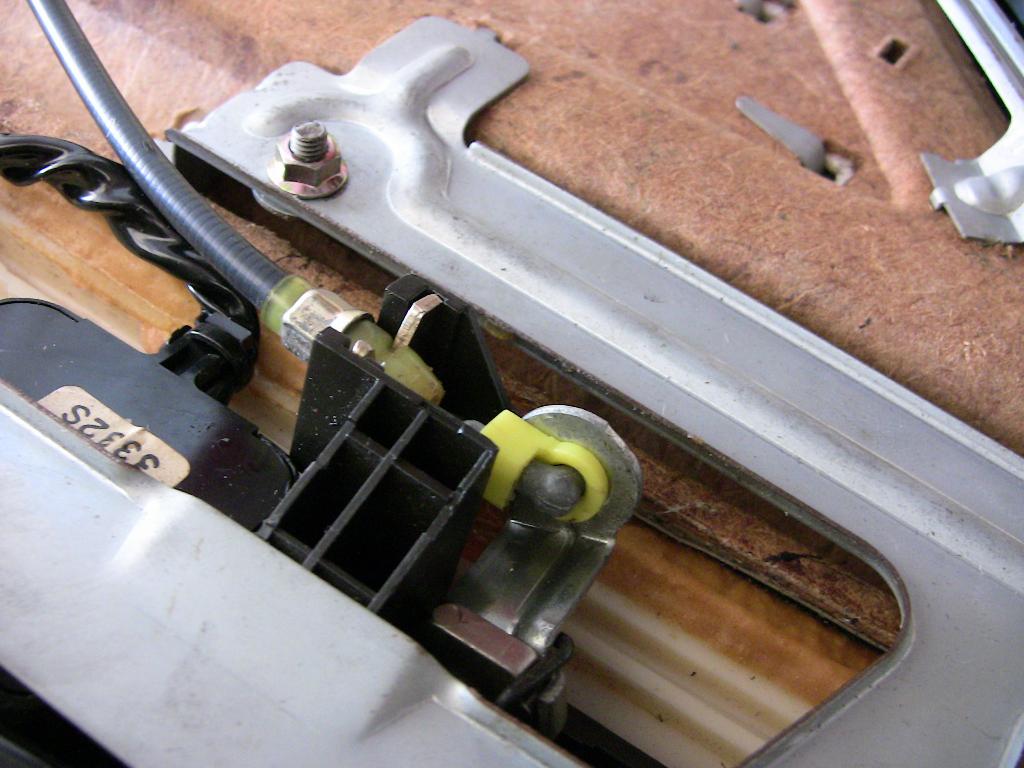
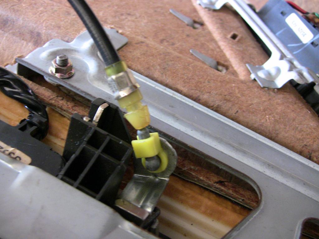
Photo 1 – Window Track
|
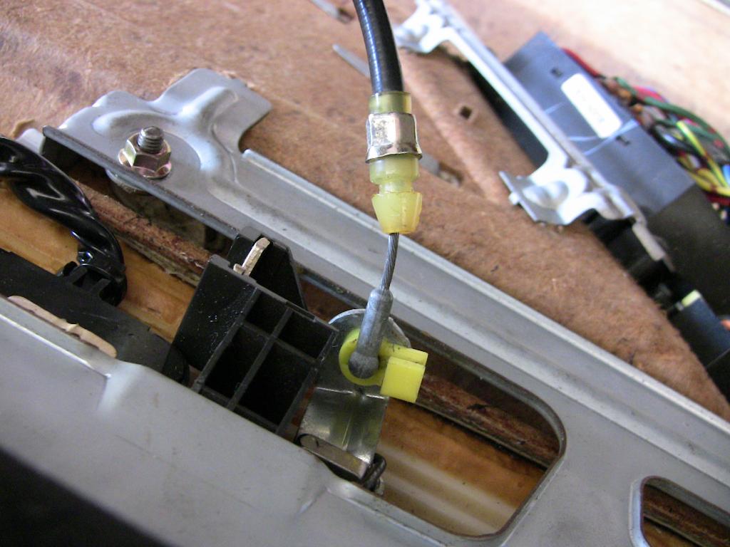
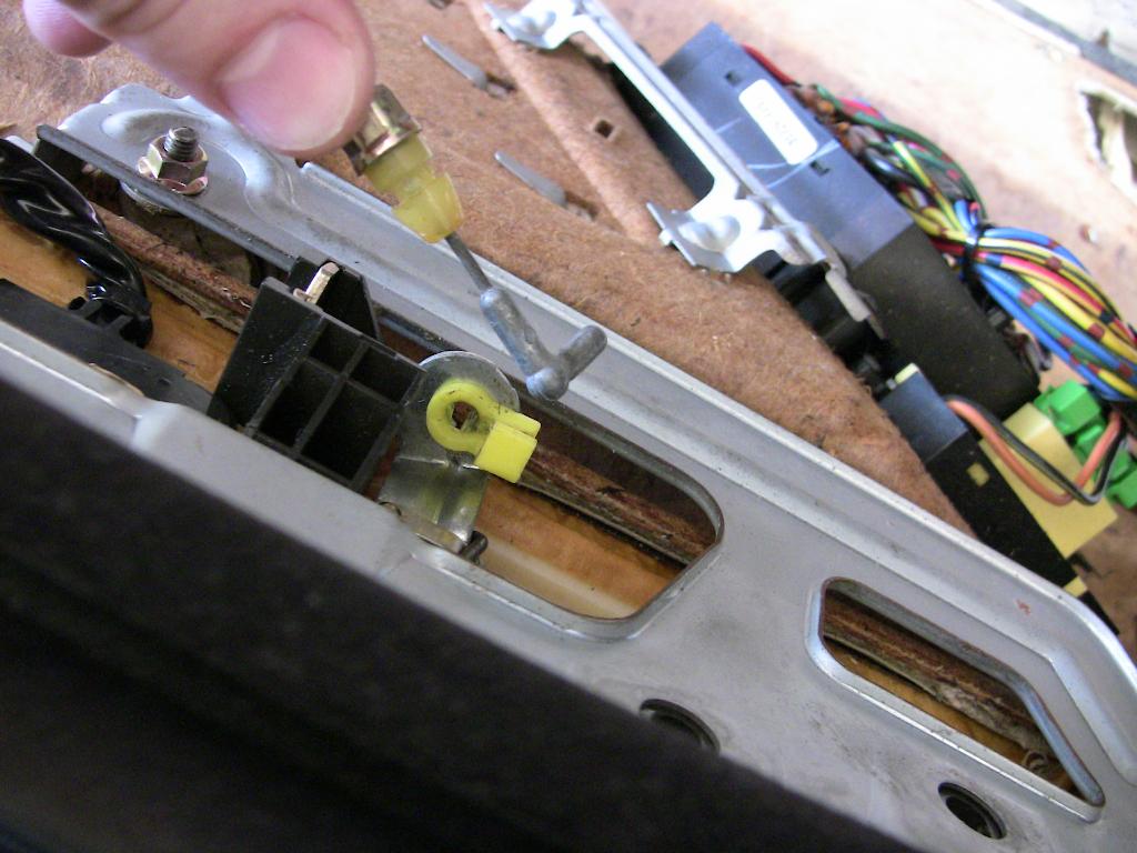
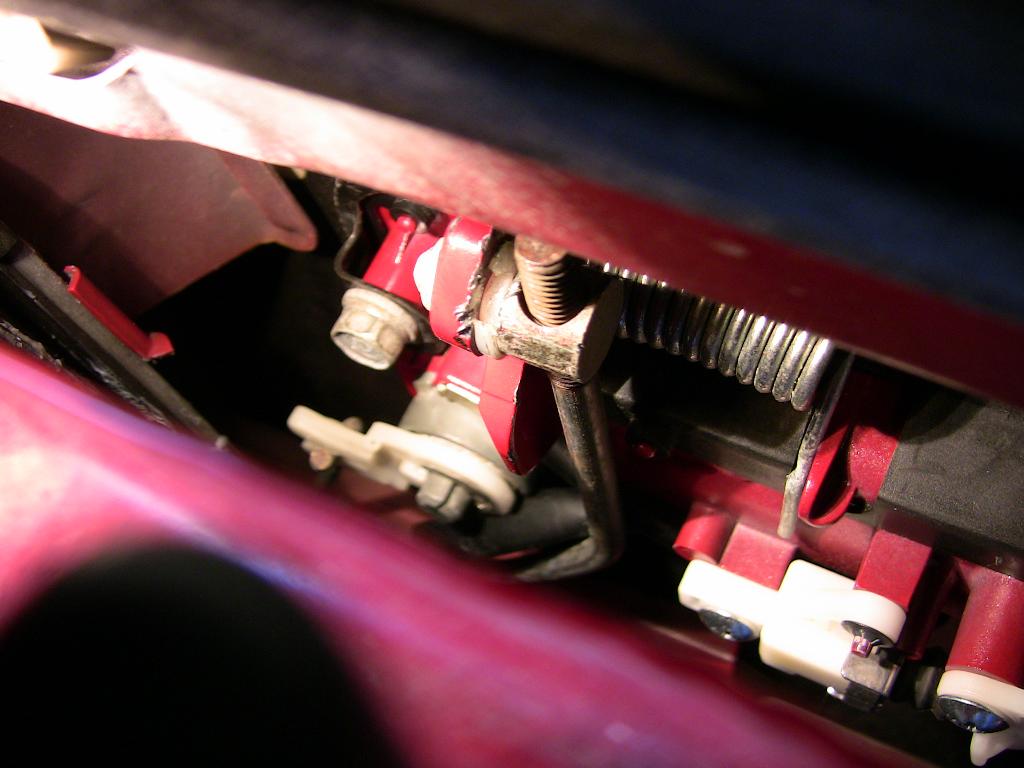
Photo 1: You’re looking at the inside of the door facing the lock mechanism. Running on a slight diagonal from top left to bottom right is the window track. This was held in by the bolt you just loosened. There is a metal support bar in the bottom right corner which runs the length of the inner door (horizontally). Note the plastic tab holding the wire harness to this bar. The lock mechanism can be seen in the bottom left behind the window track. Running from the lock mechanism up to the door handle area are three metal linkage bars and a wire harness. One linkage is for the lock plunger and another connects to the key mechanism. The third and thickest bar connects to the door handle.
 |
 |
|
Door Handle Top View
|
Door Handle Rear View
|
 |
 |
|
Photo 2 – Door Handle Left
|
Photo 3 – Door Handle Right
|
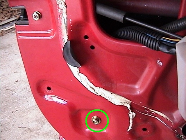
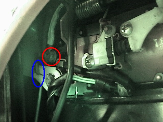
Photo 2: This is the back of the door handle (left side shown). The blue circle is the point where the key mechanism connects to the metal linkage via the white plastic piece. The red circle highlights one of two bolts that connect the door handle to the door. It’s a 10mm bolt that is removed through a small access hole in the inner door (use an extension to reach it).
Photo 3: This is the back of the door handle on the right side. The red circle highlights the other bolt that connects the door handle to the door. It’s also a 10mm bolt and is easier to remove as compared to the left side bolt.
There is a metal linkage that connects between the lock mechanism and the white plastic lever arm (blue circle in Photo 2). This lever arm is attached to the door handle (key cylinder) by a C-clip. Use a small screwdriver or a small hook tool to pull this C-clip off. Unless you’re very careful the clip will fall down into the door. Make sure you have a telescoping magnet to sweep the bottom of the door to find it. Or stuff the bottom of the door with a towel to keep the clip from falling into the nooks and crannies of the door. Once this clip is out put it somewhere safe. Then pull the white plastic lever arm off of the center axis. Once it is off that you can slide the lever arm up and off of the metal linkage.
Now remove the two 10mm bolts that connect the door handle to the door (red circles in Photos 2&3). The lock mechanism and all attachments should now be loose with the exception of the wiring harness plastic tabs mentioned in the notes of Photo 1.
Step 5: There is a rubber molding that runs in the metal window track (Photo 1). You’ll need to move the metal part of this combination to gain access to the lock mechanism. The bare metal track slides into a painted channel inside the door. Take note of how this works so you can be sure to put it back later. There are mating rails on the track and the channel. It will “fit” without properly mating these rails but it won’t work.
Step 6 : Now reach in and pull the metal track down about 1-2 inches. The rubber part will stay in place while the metal track slides down it. This should give you enough slack to rotate the metal track out of the way (counter-clockwise on the driver’s door, towards the top of the door). I found you can rest it on the metal support bar that is in the bottom right corner of Photo 1. Note the position of the window track in relation to the other parts. This will be important when you reassemble the door.
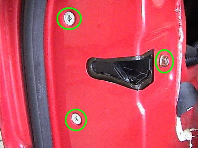
Step 7 : Unbolt the single 10mm nut (right side of the photo) and two Phillips head screws (left side of the photo) that hold the lock mechanism in. You’ll have to push in on the threaded stud after you remove the nut to get the lock mechanism to be free of the door.
Step 8 : With the door handle assembly now free to move pull it out of the door slightly. Wrap it in a towel to protect it from any slips or scratches. Using a large and sturdy flat blade screwdriver work the blade between the metal rod and plastic clip as seen in the photo below. Twist the screwdriver counter-clockwise so that the top of the blade is pressing against the metal connector and the bottom of the blade is pressing against the plastic nearest the door handle assembly. This creates a leverage force that will push the door handle assembly and rod assembly away from each other. You need a large blade screwdriver to give you the leverage and distance needed to separate the two. I have also had success with a panel removal tool (the tool that is used to pop the plastic tabs that hold the door panel on). With the right angle these can be used to pry the rod out without twisting as is necessary with the screwdriver method.
Work around the perimeter of the connector as best you can. Only certain parts of the perimeter will have the leverage positions you need for the screwdriver though. It takes some patience and a little effort but they do come apart. I know this is one part many seem to have problems with but I was able to get them apart relatively easily once I saw where to apply the force. Remember it requires a twisting motion to apply the right kind of leverage. Trying to pry them apart by pivoting on one side of the other won’t work (unless you are using the panel removal tool). Be very careful that you don’t slip or break the parts free of each other violently where your screwdriver ends up scratching your car. Protect your car with thick towels if you’re at all concerned you might slip. Once the linkage is free of the handle let the handle hang from outside the door. I flip the handle 180 degrees so the painted side faces the door. Place a towel between the two surfaces. Also note (maybe count threads) or mark the location of the rotating piece on the rod. The distance from that piece to the top of rod will affect how far your outer door handle moves to pop the door open. Wrapping the piece in some tape should fix the location while you do the other work.
Step 9: Now route the lock mechanism assembly out the large opening at the bottom of the inner door. I’ve found the best way is to let the mechanism “slip” down the outer edge of the inner door. Almost as if it were sliding down the side and then along the bottom edge.
Be careful not to twist the linkages too much or the attachment points at the lock assembly can be bent. TAKE YOUR TIME and don’t try to muscle it out. It will come out easily. If it isn’t then you’re doing something wrong. Use a flashlight and check to see what is catching inside the door. It might be a good idea to take a break before you actually start the routing and removal process.
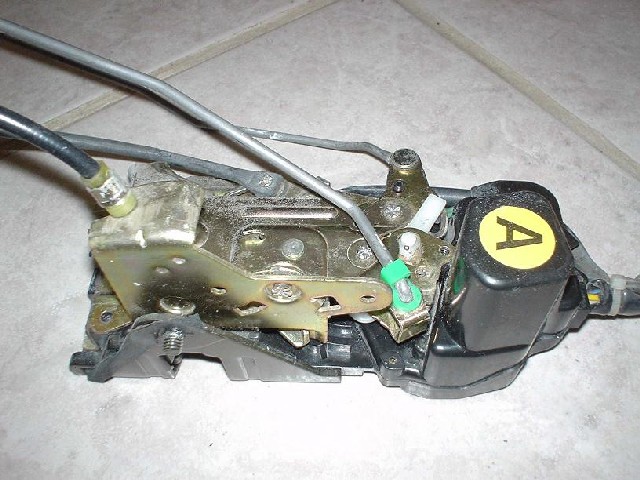
Step 10: Now we have the lock assembly out of the vehicle. Inspect it for any signs of damage that may have occurred.
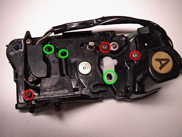
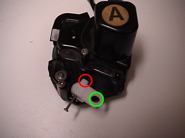
Step 11: Remove the metal linkage from the plastic lock mechanism. There are three screws that hold it on. See the red circles in the photo below (linkage already removed in the photo). Note the green circles as these points will need to be realigned when the linkage is reattached (VERY IMPORTANT). Check your piece carefully as I may have missed some screws or points of attachment in the photo. After removing the linkage it’s a good idea to put the screws back into the black plastic housing so you remember where each one goes.
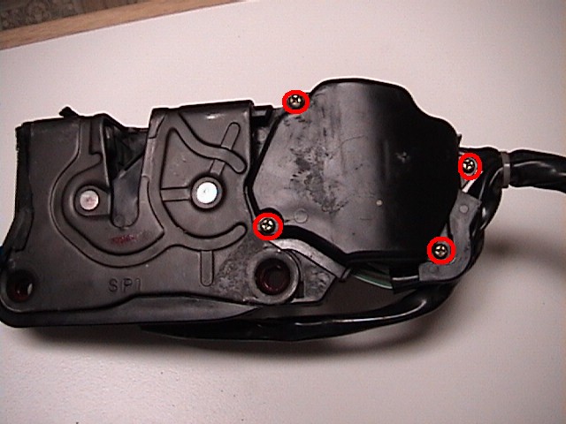
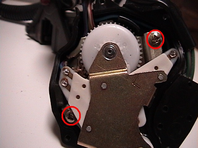
Step 12: Turn the lock assembly over and remove the four screws (red circles) that hold the actuator cover in place and remove.
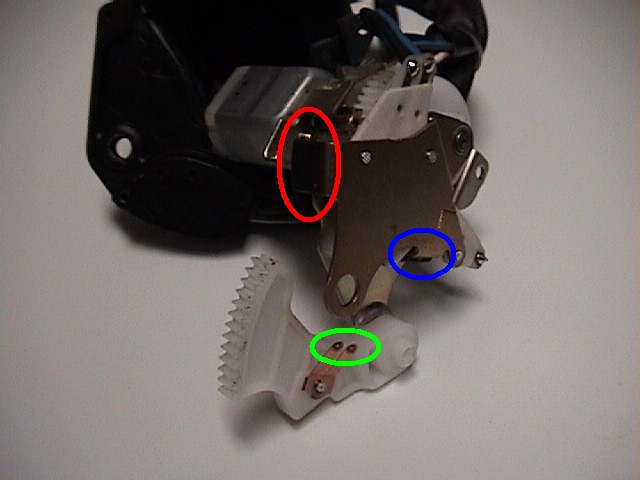
Step 13: Turn the actuator over and push the metal pin out of the white plastic piece. You’ll need to push it on the short side (red circle) to get enough pin to pull through on the long side using small pliers. Note the orientation of the white plastic piece (green circle) for reassembly and then remove.
Step 14: Turn the actuator back over and remove the two screws (red circles) that hold it in the black plastic housing. Pull the actuator innards out of the black plastic housing.
Step 15: Rotate the white partial gear (behind the green circle) away from the assembly. The area circled in green contains two contact points which may have some black build up. You can use a cotton swab to clean these and also the area that they come into contact with. Note the metal tab circled in red. This is where there should be a black rubber bumper. Yours may be missing (probably still in the housing if it didn’t drop out) or it may be damaged. This bumper(s) is what needs to be repaired or replaced. If you look closely at the area in blue you can see part of the other bumper which is still in place.
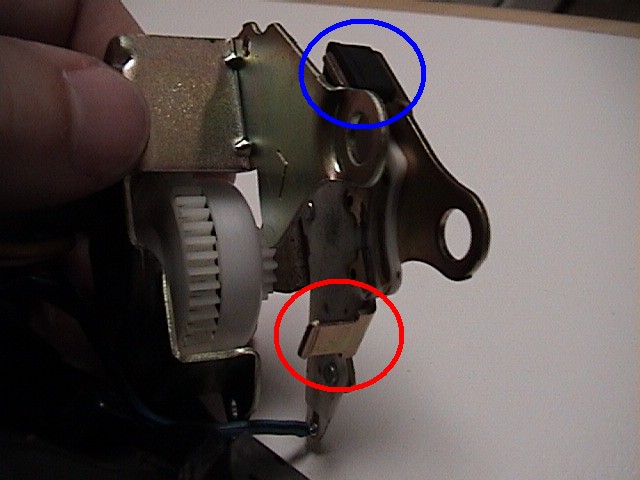
Here’s a better shot of the two metal tabs that hold the black rubber bumpers. You can see the tab circled in red is missing its bumper which is what is causing the actuator to cycle many times before stopping. The blue circle shows the rubber bumper that stops the actuator on the unlock cycle. This one is in place and undamaged. There were no problems with a continuous unlock cycle.
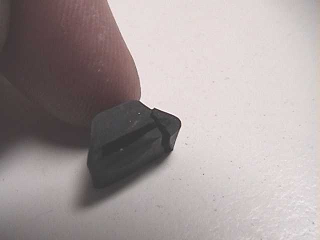
Step 16: The whole point of this adventure is to repair this ridiculous little black rubber piece. You can see in the photo that the bumper has been damaged over time from countless lock cycles and has a large tear. Note the trapezoidal shape of the bumper. Keep in mind that the narrower but thicker side (touching the finger in the photo below) faces the other bumper.
Step 17: Time to repair or replace the damaged bumper. I chose to repair the bumper rather than replace it. I doubt you can even buy these little things but you could probably get them from a salvage yard. Or you could substitute some other type of rubber material in its place. Just looking at the shape I’m thinking a piece of solid rubber with a slot cut into or maybe a piece of an old windshield wiper. I haven’t tried either of those but they might be worth looking into if repair is not an option.
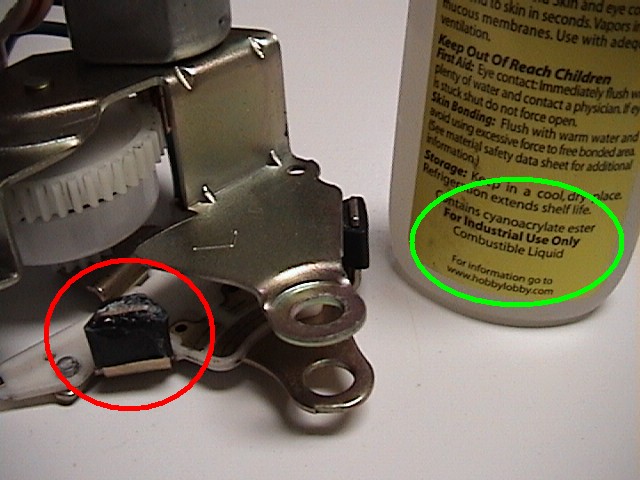
To repair this piece I used a type of super glue called cyanoacrylate (CA). You can find it at most hobby shops and it’s about $5 a bottle. Regular super glue might work as well but I really like CA glue and have plenty on hand. Put some on both sides of the metal tab and then slide the bumper over it. Add some more glue along the cracked area and clamp it in place while it dries (don’t get any on your bare skin). The problem piece is now repaired. Allow to cure fully before reassembling. Now’s a good time to take a break anyway.
Step 18: Now reassemble everything in reverse order. When reassembling the actuator and linkage assembly make sure all of the tabs and other pieces line up correctly. Route the lock assembly back through the door remembering to be careful not to bend or put undue stress on the metal linkages. Once in place all of the linkages should not be pinched or caught by metal brackets or wire harnesses. If something gets pinched after you have the door re-assembled you might be in for a lot of trouble.
The first linkage that needs to lined up is the door knob (manual lock/unlock). Make sure this is going through the proper hole in the door before lining up the other two linkages. It’s a balancing act. Insert the thick metal rod with the rotating piece into the plastic clip on the outer door handle (the rod that was pried apart with the screwdriver). Be sure to have the rotating piece at the correct location on the rod.
Drop the outer door handle into place. You will have to rotate the large hinge into the opening and then rotate it up into the top of the door. The outer door handle will not drop right in as you’re probably noticing. Now hold the outer door handle in place from the outside. Maneuver the door latch mechanism (lock assembly) so the single stud passes through its hole and the two screw holes line up. Hand tighten the screw on the stud. Add the two screws and hand tighten them.
Using a socket and extension (no socket handle) hand tighten the (2) 10mm bolts to the outer door handle. Thread the white plastic lever arm back onto the proper linkage (it may be directional, not all are) and slip it over the key cylinder axis (shaped like a bow tie). Reach in and place the C-clip on. Again, use caution when working with small parts. Have that magnet handy and/or place a towel in the bottom of the door. Then use a tool to press the clip in place. I used a small pliers to just push it on fully.
Once everything is in place go back and tighten the bolts and screws for a permanent installation. Then route all of the wires and secure them to their original location on the door panel. Put the window track back in the painted channel and secure it with the single bolt. Re-install the window remembering to tip it so the bolts pass through the door indentation. Be sure the window is in both the front track and the rear track properly. This includes ensuring the rear track outer seal (around the window’s outer opening, it’s like a wind sealing flap) is not pinched under the inside of the window (the outer seal should be on the outside).
hi, new to the site, thanks.
I also have that kind of problem with my car now. tnx 4 posting.