Posted in
  Tags:
Tags: Replace the Axle (Also Known as the CV Half Shafts) on a 2005-2010 (First Generation) Scion TC
Works For:
2005, 2006, 2007, 2008, 2009, 2010 Scion TC Models
Source: ClubScionTC
I figured I’d help everyone out that’s interested b/c I searched through hell and high water just to get a crappy how-to online. Most of the directions were basic, so you really had to pay attention to what you were doing.This would be for OEM axle replacement. I just needed new ones b/c the old ones were leaking at the inner boot, so this isn’t for any performance gain over stock.
Equipment needed:
-Metric 6 point sockets (10, 12, 14, 17, 24)
-12 point 30mm axle hub nut socket (for OEM axle)
-6 point 32mm axle hub nut socket (for new axle)
-Beveled center punch that’s about 3/32″ thick
-Breaker bar/wrench
-Torque bar/wrench
-Tie rod separating fork
-Hammer
-Cotter pins
-3 quarts gear fluid
-Pry bar kit (usually comes with 3 different sizes…I used the medium and large bars)
-Jack stands
-Floor jack (or whatever you have to get the car up on the stands)
-Flat head screw driver
-Metal cutters/snips/wire cutters
Step 1:
Locate your jack position under the center of the motor (reference this DIY for a picture:http://clubsciontc.com/fo…mission-fluid-swap-7837/)
Step 2:
Loosen your lug nuts BEFORE jacking the car off the ground (unless you have an impact gun).
Step 3:
Jack car up and place on jack stands (again, reference this link to see picture:http://clubsciontc.com/fo…mission-fluid-swap-7837/)
Step 4:
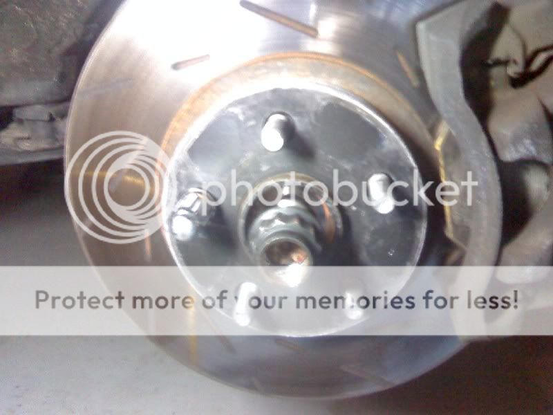
Remove tires and locate the axle hub nut. This is a black nut (if you have an OEM axle) that is a 12 point 30mmnut. You will notice that there is a groove in the axle shaft that tapers up towards the nut. You must use the center punch to bend the inner edge of the nut upwards to allow you to loosen it off the shaft. Once you have the lip lifted to clear the threads, put the wheels back on but REMOVE YOUR CENTER CAPS FIRST. If you can remove your center caps before doing anything with this install, you will save yourself a few steps.
Once the tires are back on, just put 2-3 lugs back on to support the wheel on the hub when you lower the car.If you have a buddy there, you can skip this step by having him/her step on the brake as you loosen the axle hub nut…again, it saves a few steps. When the tires are on the ground and enough car weight is pushing on them to prevent them from spinning, grab your breaker bar and 30mm 12 point axle socket and remove both axle hub nuts.
Once they are off, lift the car up again and remove the wheels. This is what you will have:
Step 5:
Next, I have no pictures for this b/c it was dark in the garage, so bare with me. PM me if you have questions about it. On the inside of the hub knuckle (big metal portion where your rotor sits and is mounted to 2 nuts on the strut), you will find a small black wire that leads up to the strut and then up to the fender. The end that is on the hub is the ABS sensor. Using a 10mm socket, loosen this CAREFULLY and set it aside. It’s magnetic, so it’ll stick to metal a bit. Make sure to keep this clean of debris prior to re-installation. Follow the wire up to the strut and you will see a bracket holding this wire in place. Using a 12mm socket, remove the bolt and get the bracket and ABS sensor as far out of the way as possible, BUT BE CAREFUL NOT TO DAMAGE THE WIRE!
Step 6:
On the back of the axle hub, you will see the outer tie rod end connected to the knuckle coming from the steering rack and pinion. This will require you to cut off the cotter pin to be able to remove the castle nut (looks like a little castle, so you won’t miss it). Using a 17mm socket, remove the castle nut.
Step 7:
After the castle nut is off, grab the tie rod fork and wedge it under the knuckle seat for the tie rod and right against the tie rod bushing. Take care not to tear the bushing (you can rub some grease on it to lower the friction if you want). Grab a hammer and hit the back of the fork wedging it under the knuckle seat. Keep at it b/c this could take some time depending on the amount of rust. Once the tie rod pops out, just move it aside and let it hang from the steering rack.
Step 8:
Using that same 17mm socket, locate the lower ball joint at the bottom of the back side of the hub knuckle. The point where it connects to the front lower control arm will have 2 nuts and 1 bolt (17mm for all of them). Remove them and set aside.
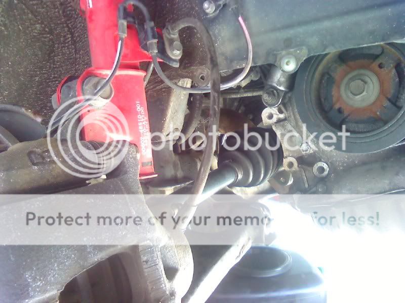
Once remove, use the pry bar to wedge the entire knuckle off of the control arm. See picture below for reference to past steps:
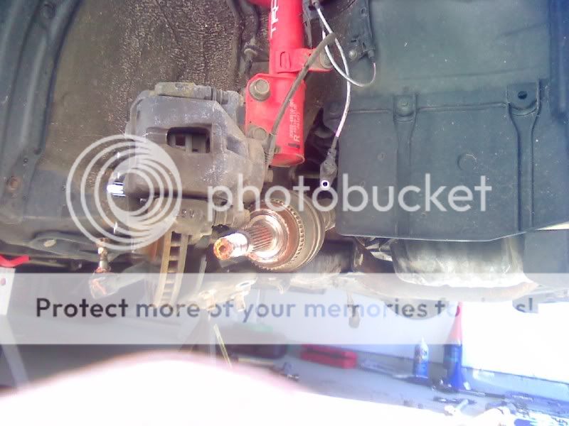
Note: Tie rod off to the left with castle nut on top and lower portion of knuckle shows ball joint off of control arm. Also, the wire hanging to the right is the ABS sensor wire.
Step 9:
This step ONLY goes with the passenger side as the driver’s side does not have an intermediate shaft and bearing assembly.
Locate bearing assembly on intermediate shaft.
You will see 2 bolts (14mm) on the bearing assembly…one on the bottom and one on the top. Remove both bolts and set aside. With a hammer, TAP the edge of the bearing assembly to break any surface rust free. Should only take 2-3 taps and it’ll separate.
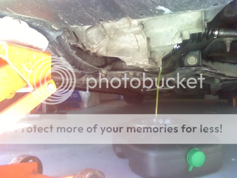
This is where you may want to either position a pan under the transmission seal to catch fluid coming out, or best would be to drain transmission fluid prior do this step. Reference this thread for transmission flush and fill:http://clubsciontc.com/fo…smission-fluid-swap-7837/.
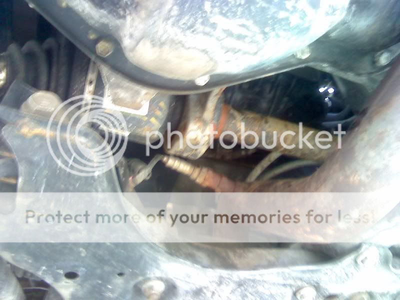
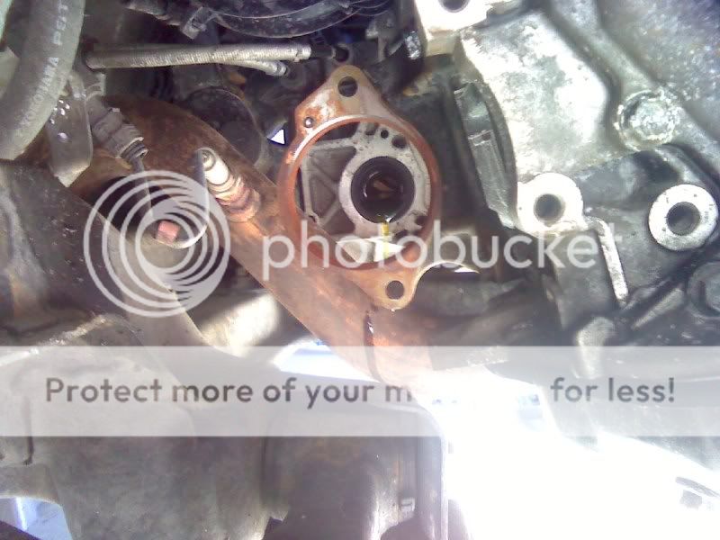
Once a gap forms between the bearing assembly and the support housing, use a pry bar or flat head screw driver and work the bearing assembly out of the housing. You will be pulling the entire intermediate shaft out of the transmission along with the axle at this point. Take care not to damage the metal/rubber seal on the transmission housing. You should be seeing this as these steps progress:
After bolts have been remove and shaft taken out:
Step 10:
At this point, I rubbed some bearing grease in that support bracket you see in the above picture. That just makes the seating of the new bearing much more fluid.
Step 11:
Slide new axle CAREFULLY through bearing support housing and into transmission. The bearing assembly will have an alignment in, so no worries when it comes to matching the bolt holes up. Once assembly is flush with bearing support, install the 2 14mm bolts back in place (torque to 40 ft/lbs)
Step 12:
Use some muscle and get the head of the axle shaft back into the hub knuckle and aligned with the teeth. I put some bearing grease on the splines to make it slide in easily. Hand tighten the new hub nut in place.
Step 13:
Using the pry bar again, pop the lower ball joint back onto the front lower control arm and reinstall the 2 nuts and 1 bolt (all 17mm). (Torque to 69 ft/lbs)
Step 14:
Slide tie rod end into knuckle seat and tighten castle nut. (Torque to 39 ft/lbs). Slide cotter pin through eye of castle nut and bend both ends back to lock nut in place. Trim off excess cotter pin material with cutters.
Step 15:
Clean off ABS sensor and housing prior to install. Route sensor back to housing and using the 10mm socket, bolt in place. {Torque to 6 ft/lbs). Reinstall support bracket onto strut housing. (Torque to 15 ft/lbs).
Step 16:
If you did the work with a buddy, have them apply hard brake pressure while you torque the new axle hub nut. (Torque to 159 ft/lbs). Get your center punch and stake the nut in the axle shaft groove. Just find the groove on the head of the axle shaft, place center punch on lip of nut over the groove, use a hammer to bend the lip a little bit…and that’s it. If you did this alone like I did, repeat the step where you mount placed the tire back on and lower it to the ground to make good contact. Torque the axle hub nut and then your lug nuts. (Torque lugs to 80 ft/lbs). Replace center cap.
Step 17:
Refill transmission with proper amount of your selected fluid. [i]75W-90 Royal Purple shown. 2.6 quarts[/b]
For the driver’s side of the vehicle, you have to use some muscle in reinstalling the axle and make sure the C-clip on the inner portion of the axle is aimed with the open end down upon re-installation. The rest is the same as the passenger side for removal of tie rod end, ball joint and ABS sensor (re-installation as well).
Reason for replacing axles:
Both inner boots were leaking. I believe this was caused by the winter we had up here and water getting into the edges of the boot and freezing. When it froze, the band expanded enough to cause the grease to start working its way out. To prevent a MASSIVE clean up under the car and potential transmission damage to a blown out CV joint, I went ahead and replaced both sides with GSP axles (new) from Advance Auto. Got them for about 85$ each.
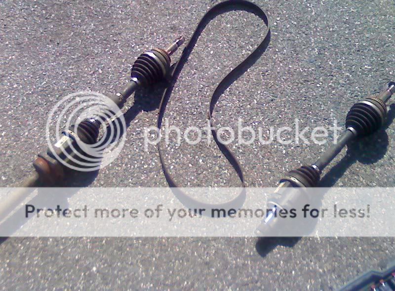
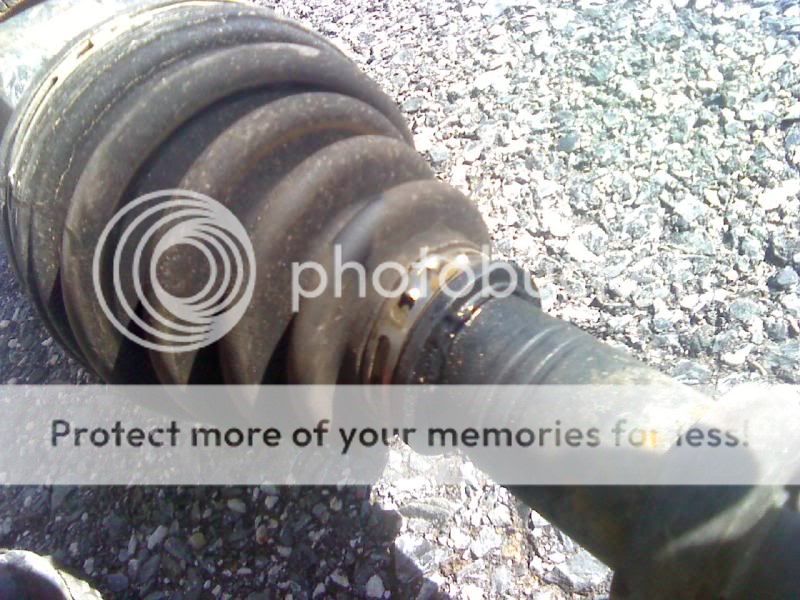
Old passenger side vs. new passenger side:
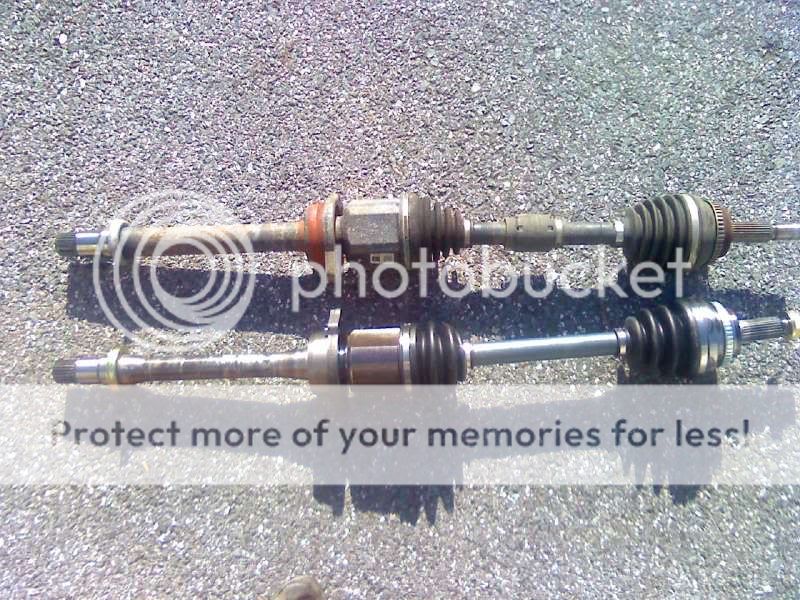
Old has a counter weight on the shaft for vibration control, but I haven’t really noticed too much of a difference with the new one. Having urethane motor mounts should help keep this shaft aligned nice and straight on hard launches. For a DD, I’ll be good to go. I’ll report back if anything happens.
Oh, I ended up replacing my serpentine belt too b/c some grease from the passenger side inner boot was getting on it. Here’s all the old equipment: